
Forest Engineering- Offsets in Chain Surveying
Offsets
Offsets are lateral measurements from the chain line taken to objects such as---corners of buildings, fences and hedges, banks of streams, trees and poles, etc., to the left or right of the chain lines, which are required to fix the details of the survey.
Types of Offsets
There are two kinds of offsets (1 ) Right, Rectangular _Or Perpendicular Offsets, e.g., CD and EF in Fig. 4.2, which are taken at —tight angles to chain line AB at the points D and F to locate the two corners of a building. In the strict sense, offsets are always taken at right angles to the chain line. Measurements_ taken at oblique angles (i.e., other than right angles) are known as oblique or tie offsets, e.g., EG and EH in Fig. 4.2. it will be easily appreciated that whereas one right offset is sufficient to fix the point, at least two oblique offsets are necessary for the purpose. Oblique offsets are also sometimes taken to check the accuracy of plotting by perpendicular offsets, and vice versa.
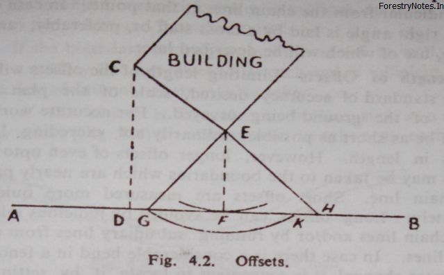
For accurate plotting, the offsets should be short, i.e., less than 15 meters. These are taken with metallic or steel tape ; shorter ones can be taken with an offset rod. Every offset involves two measurements : (i) distance along chain line, i.e., chainage at which taken (e.g., points D, G, F or H in Fig. 4.2) and the length of the offsets (e.g., CD and EF, or EG and EH in Fig. 4.2).
These are recorded appropriately in the field book. Sometimes when a tape is available, a perpendicular offset may be taken by merely swinging the tape, e.g., if an offset is to be taken to the corner E of the building (Fig. 4.2) the leader holds the zero end of the tape at E and the follower, carrying the tape, swings it along the chain in a short arc about the point E as centre and finds the point F of the minimum reading, which is the foot of the perpendicular from E to the line AB. Such an offset, as EF, thus taken by swinging the tape in an arc along the chain line, is called a Swing Offset. This may also be taken by another method : hold the zero end of the tape at E and stretch the tape over the chain at r and note the reading on the chain and the tape. Then swing the tape until the same reading meets the chain again at K. Bisect GK at F, and join EF, which is the required offset. It may be verified for a check that reading El: is the minimum on the tape when it is swung on the chain line. Perpendicular direction of short offsets, up to about 10 meters, may be judged by the eye or laid out by swinging the tape. It can also be estimated by facing the forward station, stretching the arm side ways at right angle and moving forward and backward , when the1 arm points to the object to be offsetted, the object would be perpendicular from the chain line at that point. In case of a long offset, right angle is laid by a cross staff or, preferably, an optical square, use of which will be described later.
Length of Offsets
Limiting length of the offsets will depend on the standard of accuracy desired, scale of the plan and the nature of the ground being surveyed. For accurate work, offsets should be as short as possible, ordinarily not exceeding 15 to 20 metres in length. However, longer offsets of even upto 40 to 50 metres may be taken to the boundaries which are nearly parallel to the chain line. Short offsets are measured more quickly and accurately. Long offsets can be avoided by judicious selection of main chain lines and/or by running subsidiary lines from the main chain lines. In case there is a considerable bend in a fence, hedge or a water channel, it is convenient to locate it by setting out a subsidiary triangle as shown in Fig. 4.3.
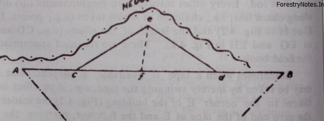
Instead of taking long offsets from the main survey line AB to locate the outline of the irregular hedge, a subsidiary triangle cde is laid on the chain line AB so that it is well-conditioned and the lines ce and de run sufficiently close to the hedge, so that offsets to various points on the hedge are tAcen nom the lines ce and de instead of taking long offsets from the line AB.
Number of Offsets
The number of offsets will depend on the nature of physical features to be plotted, the scale of the map and the degree of accuracy aimed at. The general rule is to take as many offsets as are necessary to define the outline of the object clearly and accurately. However, it is advisable to take an offset too many rather than too less. Based on this general principle, following guide-lines are provided for offsetting various types or objects: — (i) If the object is round (circular in outline), an offset should be taken to the centre and its radius noted. (ii) If the boundary is straight, as in case of a wall, road, canal or a railway line, an offset to its each end is sufficient. If it is long, a few additional offsets may he taken. (iii) If the object is irregular in outline, such as a curved road or a nallah (Fig. 4.4) an offset should he taken at each bend
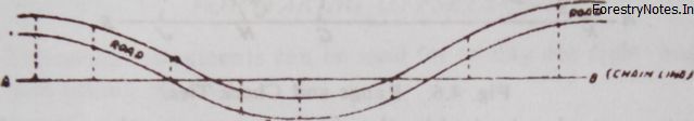
or change of direction. (iv) In case of curved foot-paths or roads, etc. (Fig. 4.4), offsets should be taken to the beginning, middle and end of the curve, and also to some points in between. (v) To locate a gate, both posts or pillars should he located by offsets and ties ; width of the gate and dimensions of posts or pillars are also measured. (vi) When an object such as a fence, hedge or a road, etc., crosses a chain line, the point of intersection is noted. Offsets should also be taken to the points in it on ,either side of th point of intersection to determine its direction.

