
Cross Staff, Prismatic Compass,Traversing with chain and Compass
Cross Staff
(i) Wooden Cross Staff—
It consists of a block of wood, square or round, about 4 cm thick, in which two fine saw cuts, about a cm deep, are made accurately at right angles, and a hole is bored below this block so that it can be rested on a staff, I to 1 meter long To facilitate observations, the block is sometimes provided with 2 pairs of vertical slits at the ends of the grooves, giving two lines of sight at right angles.
(ii) Open Brass Cross Staff—It is mounted on a spiked pole so as to fix it in the Staff. ground. At the upper end, two pairs of brass sights, at right angles to each other, are provided in the form of a frame. These provide two lines of sight, mutually at right angles to each other.
(Ill) French Cross Staff: It consists of a brass box octagonal or cylindrical in shape, with thin long slits along the sides and parallel to its axes. The French Cross Staff has an alternate vertical sight slit and an opposite vertical window with a fine wire hair, or a vertical horse, on each of the four sides. These are used for setting out right angles. On the other four sides are vertical slits, which are at 45° to those previously mentioned, for setting out angles of 45°.
Method of Use of a Cross Staff
(a) To set out a right angle:
Let AB be the chain line on which it is required to set out a right angle at E. Fix a ranging rod at F on chain line AB, at some distance from E. Set up the cross staff at E, turn it Hail the rod at F is sighted through one of the grooves or lines of sight. Sighting through the second line of sight (without moving the staff) establish the second line of sight along EC, at right angle to the chain line AB at E ; fix a ranging rod at G ; GE is perpendicular to AB at E.
(b) To find foot of the perpendicular from the object to a chain line (i.e., to take an offset) :— Let AB be the chain line (Fig. 4.10) and G the object to be offsetted, i.e., foot of the perpendicular E on chain line AB is to he established and length of offset GE to be measured. Set up the staff on the chain line AB, approximately at the required point, sighting the forward rod at F. Now sighting through the second pair of sights, move forward or backward, until the object G is bisected; this point of observation E is the required point.
Checking the accuracy of a Cross Staff
Lay out a perpendicular with reference to one pair of sights and check it by means of the other. If necessary, the two lines of sight may be re-set so that these are correctly at right angles to each other. Compass Surveying When an accurate map is required to be prepared, plane table or chain survey is not appropriate. In that case, traversing by compass survey can he used. It is preferred in plain areas with obstacles. The area should not have iron ore, otherwise accuracy will not be achieved. Measurements The direction of a survey line may he obtained either by (I) the horizontal angle between the line and the line adjacent to it and (ii) bearing which is the angle between a fixed line of reference called the meridian and the line.
Instrument commonly used for this purpose are the theodolite and the compass. The theodolite can measure the angle between two lines directly. The compass on the other hand, measures only the hearing. There are various types of compass like prismatic compass and surveyor's compass
Prismatic Compass
The prismatic compass is used for working with speed but not very accurately. It consists of a cylindrical metal box of about 80 to 120 mm diameter. In the centre there is a pivot (2) which carries a magnetic needle (3) attached to a graduated aluminum ring (4) with the help of an agate cap (5) The ring is graduated from 0° to 360° with a minimum of half divisions are made in the anticlockwise direction with 0° to the magnetic south and 180° in the magnetic north.
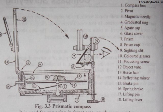
Fig: Prismatic Compass
It is used for surveying in forest area, rough work, road surveys etc. Its reliability is less in places where magnetic rock or iron ore is present.
Working of the Prismatic Compass
The prismatic compass is mounted on a tripod by screwing it to a vertical spindle in a ball and socket joint. With this arrangement, the compass can easily be levelled, routed in a horizontal plane and fixed in any position. After this, the following 3 steps are followed:
(1) Centering—The compass is placed approximately over the station and a stone is dropped from below the centre of the compass. For accurate centering. the stone should fall over a peg fixed at the station
(2) Levelling—By means of the ball and socket arrangement, the compass is levelled so that the graduated ring along with magnetic needle can swing freely.
(3) Observation of bearings After centering and leveling,---the prism is adjusted till the graduations on the ring are visible when looked through the prism. The compass box is turned until the ranging rod to be sighted is bisected by the horse hair when looked through the slit above the prism. As soon as the ring comes to rest, reading is/taken through the prism sighting the ranging rod simultaneously.
Surveyor’s Compass
This is similar to prismatic compass except that another plain sight with a narrow vertical slit is placed instead of reflecting prism and it carries an edged bar needle on a pivot. The surveyor's compass is shown in Fig Prismatic Compass
The graduations are made in quadrantal system in which zero is in the North South and 90° is in East and West.
Traversing with chain and Compass
During traversing with the compass, the free or loose needle method is used for fixing the direction of the survey lines_ The compass is set up at each of the successive stations and the fore and hack bearings of each of the lines are read and entered in the field book. The field work consists of reconnaissance, marking of stations. running of survey lines, collecting details and making field notes.
While selecting the stations for traversing, the following points should be kept in mind :
1. Stations should be visible from each other.
2. Chaining between the station should be easy.
3. The lines joining these stations should pass as close to the boundary and other objects.
4. They should be as long as possible.


